five step procedure
Properly installed TVSS can save ESPs from lightning damage and switching surges and prevent lost production. A TVSS improperly installed can actually cause ESP damage. From field surveys, reports and technical papers on oil-field power distribution, SubSaver has determined the following are necessary for proper installation:
5 Step Grounding Procedure
Each component needs a 4 wire Transient Voltage Surge Suppressor (TVSS).
TVSS on submersible pump must ground to the well head. Dry clay does not provide sufficient ground impedance to dissipate a lightning surge.
TVSS must mount on the junction box. Surges will always travel the shortest distance to ground. To protect the ESP motor, mounting the TVSS on the junction box next to the well head is the best protection.
Hot wires from the transformer should not be grounded. Transformer grounding is done on the pole. This forces the surge the short distance into the shield wire instead of the direct connection to the ESP.
Separate ground wires are necessary for the disconnect at the pole, the TVSS on the variable speed drive, and the TVSS on the junction box at the well head. A surge will follow the shortest path to the ground. If all three devices are on the same ground wire, the ground wire may conduct higher voltage backwards through the TVSS into your electronic equipment.
Theory, experience, & justification
Below is an explanation for each of the five steps in the grounding procedure listed above. These are based on our knowledge and experience.
Without a ground wire connected to the wellhead that connects to the ESP motor housing, it is impossible to limit voltage impulses phase-to-housing. These are the cause of most insulation failures.
Acceptable wellhead grounds are shown in Fig. 1 and Fig. 2. A service post, Fig. 3, is recommended, but a welded bolt head and ground lug are acceptable. Ground (pipe) clamps are strongly discouraged due to the very poor electrical connection and related safety considerations.
Junction box mounting, Fig. 4 and Fig. 5, puts the TVSS as close to the wellhead as possible thereby providing the best impulse limiting.
Ungrounded power has been the industry standard for over 80 years, because oil production is a continuous process and pumping can continue after the first downhole short. Grounding the windings feeding the ESP is always done up on the pole, where connecting wires to the lightning arrester common or shield wire are very short. This increases the likelihood of lightning damage.
Separate ground wires only bonded together at the wellhead can prevent the interaction of lightning arresters and TVSS. This interaction is the main reason for uncertainty about TVSS effectiveness. Failure to separate ground wires has caused TVSS to damage ESPs. The way grounds should be separated for switchboard ESP operation is illustrated in Fig. 6. For VFD operated ESPs, please refer to Fig. 7 & Fig. 8.


Welded Bolt Head and Ground Lug
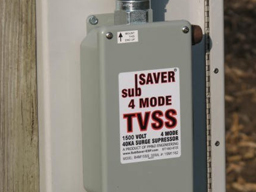
SubSaver-4M
Junction Box Mounting
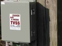
SubSaver-6M
Junction Box Mounting
Click to enlarge image.
Separate Grounding for lighting arresters and disconnect
Ground wire through the disconnect must be broken, cf. Fig. 8
If necessary, install additional ground rod at VFD.
Click to enlarge image.
variable frequency driving grounding with 3 wires
Installation Details
All Subsaver® products are factory tested six ways: three phase-to-phase and three phase-to-ground to insure performance to specifications. However, TVSS effectiveness requires close attention to grounding as detailed in the previous diagrams.
Installation of both SubSaver TVSS products is the same. Subsaver-4M (40kA per mode, models B4M) and Subsaver 6-M (40kA per mode, models H6M) were designed for external mounting on a junction box. A large ground lug is provided on the outside of the TVSS for connection of the ground wire. This most important ground wire runs from the wellhead to the TVSS. The external lug makes it easy to check if the ground wires (green THHN insulated, #2 AWG stranded copper) are connected as required. The small green ground wire in the elbow connects internally to the ground lug in a steel junction box or the back plate ground lug in a fiberglass junction box.
Three black phase wires should be cut about six inches longer than necessary and then connected to the three terminals in the junction box. Phase wires are labeled A, B, and C for testing purposes. Usually these are connected in order from left to right to the three terminals, but it really makes no difference in what order they are connected.
Cable armor between wellhead and junction box should be grounded at the wellhead with an appropriate size pipe clamp and #6 AWG bare copper wire. Other cable armor should be grounded as illustrated in the previous diagrams with #6 wires. At the junction box, armors should not come in contact with each other or a metal box. It is important that no connection between the cable armor and the ESP System Ground contacts the Power System Ground anywhere except at the wellhead. Armor grounding is essential for personnel safety.
Service posts are available from Burndy (model K2C23B1) or Penn-Union (model SCS-4A1). Posts should be installed in the lower flange to avoid workover problems.
A “hot work” permit will be required if natural gas is present. Check that well casing is sealed before attempting a welded bolt head ground. Connection to the lower flange is recommended.If the VFD is trailer-mounted, the junction box should be fiberglass for electrical isolation.
Once all ground connections are made they should be coated with a sealant (glyptol, etc.) to keep moisture out and minimize corrosion.